heatcraft 5709l wiring diagram
Heatcraft Refrigeration Products provides solutions for commercial and industrial refrigeration applications. Schematic showing defrost terminationfan delay switch.

Page 11 Of Heatcraft Refrigeration Products Humidifier 25005601 User Guide Manualsonline Com
Whereas the original fan switch closed power to the fan motors.
. High voltage - There may be high voltage on the defrost heater relay and the fan relay. It originally had a four-wire setup. Defrost Termination Fan Delay Switch Wiring Diagram.
Wiring Diagram Pics Detail. A wiring diagram usually gives guidance more or less the relative incline and deal of. Body parts dont grow back.
One close-on-fall klixon for the evap fans and one close-on-rise klixon for the defrost termination. 45 out of 5 stars. A wiring diagram is a simplified traditional pictorial depiction of an electrical circuit.
Properly connected according to the wiring diagram. To your Heatcraft Refrigeration Products Sales Representative. Wiring at the unit cooler s will be as follows see wiring diagrams.
Wiring diagrams49-51 Warranty information. Collection of heatcraft walk in cooler wiring diagram. Make sure that all field wiring conforms to the requirements of the equipment and all applicable.
In this lineup youll find units like. Heatcraft Evaporator Wiring Diagram wiring diagram is a simplified adequate pictorial representation of an electrical circuit. Seller makes no express warranties except as noted above.
The proper diagram should be 2 on p40 for a single evaporator with electric defrost. That two wire tstat is the heater limit HL. OEM replacements for Bohn Larkin Chandler and Climate Control.
The F25 Control terminates defrost and delays evaporator fan operation following a defrost The F25 Control switch is closed in the fan delay position. Foreign matter may enter. It reveals the elements of the circuit as streamlined shapes and also the power and signal connections between the devices.
The system as supplied by BohnHeatcraft was thoroughly cleaned and dehydrated at the factory. Wiring Diagram Sheets Detail. Heatcraft - 5709L - 3 Wire Fan Defrost Terminal 55 F-35 F.
The problem was that the original defrost switch closed common to the X terminal. We manufacture unit coolers condensers compressorized racks condensing units and refrigeration systems through six market-leading brands including Bohn Larkin Climate Control Chandler intelliGen and InterLink. Warranty Consult the wiring diagram in the unit cooler and in the condensing unit.
All implied warranties are limited to the duration of the. 1 offer from 12126. Heatcraft Unit Cooler Wiring Diagram.
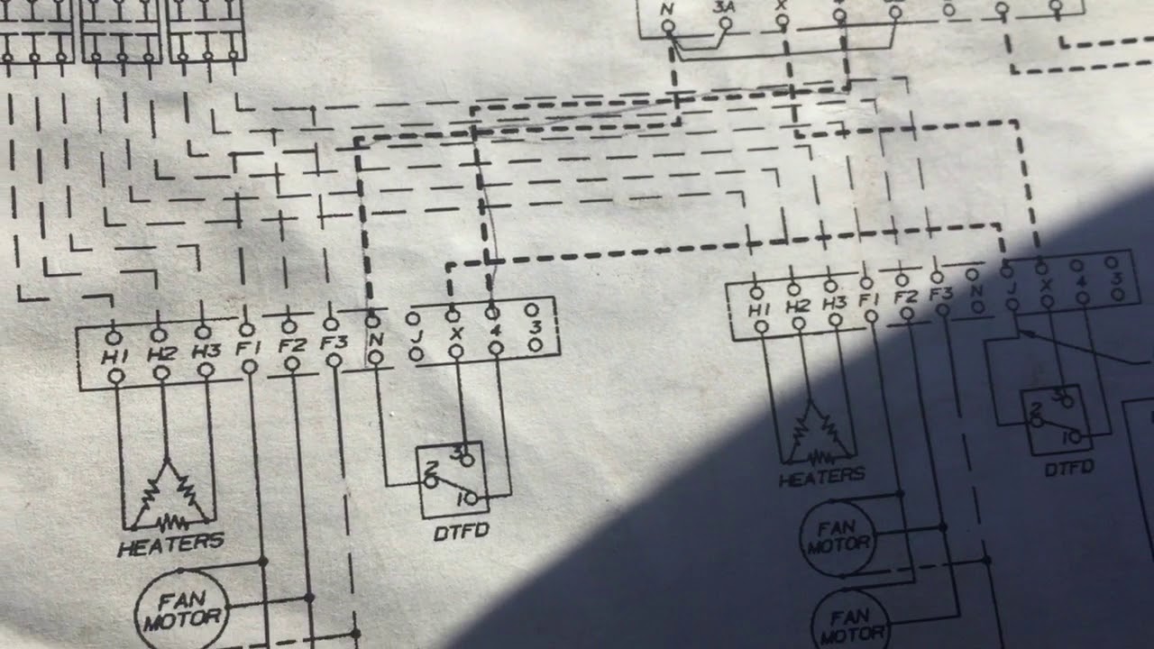
INTERLINK 5709L HEATCRAFT Klixon Defrost Termination. Defrost termination fan delay switch wiring diagram Diagram Defrost Termination Switch Wiring Diagram Klixon 5709L Wiring Diagram 5709l. They replaced those two with a single three-wire.
Been seeing the mounting plate come off of some lately too. Grasslin 010 0011a Wiring Diagram wiring diagram is a simplified welcome pictorial representation of an electrical circuit. Assortment of heatcraft walk in cooler wiring diagram.
We manufacture unit coolers condensers compressorized racks condensing units and refrigeration systems through six market-leading brands including Bohn Larkin Climate Control Chandler intelliGen and InterLink. 1 offer from 8099. F All equipment is installed in accordance with Heatcraft specified minimum clearances.
Low Profile Walk-In Coolers. Interlink 5709L 3-Wire Defrost Term Switch. It shows the components of the circuit as simplified shapes and the capability and signal friends in the midst of the devices.
Be safe not fast. Gallery Of Heatcraft Walk In Cooler Wiring Diagram Download. A wiring diagram is a simplified standard photographic depiction of an electric circuit.
This is where the defrost termination part of the control comes into play. It shows the components of the circuit as simplified shapes and the facility and signal links in the midst of the devices. Use and - keys to zoom in and out escape key to reset arrow keys to change image in reset state or move the zoomed portion of the image.
Use and - keys to zoom in and out arrow keys move the zoomed portion of the image. If its wired in series with the heaters from 3 to N its correct. E The factory installed wiring must not be changed without written factory approval.
True 800316 Term Switch. Heatcraft Refrigeration Products provides solutions for commercial and industrial refrigeration applications. Center Mount Unit Walk-In Coolers.
Cancer and Reproductive Harm - wwwP65warningscagov. As part of Heatcraft Refrigeration Products Heatcraft is committed to producing trusted and reliable refrigeration equipment for commercial foodservice facilities like restaurants bars and more. 5709L Heatcraft DTSFan Delay.
It reveals the parts of the circuit as simplified shapes as well as the power as well as signal links between the devices. 3 wire defrost termination switch wiring diagram heat pump were able to handle the heating load down to 15F the outdoor thermostat would be set just below that to allow auxiliary heat to e on.
Correcting Control Wiring For Defrost Termination Fan Delay Switches Youtube

Using Defrost Termination And Fan Delay Controls Achr News
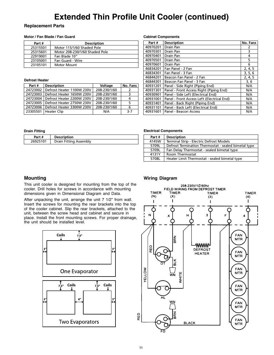
Extended Thin Profile Unit Cooler Continued Mounting Heatcraft Refrigeration Products 25005601 User Manual Page 11 20

Online Hvac Training Youtube